“Alexa, Turn On My Computer.”

A year or two ago, I bought myself an Amazon Echo. I was curious as to what the device could do, and it was on sale at the time. The fact that I’ve had a facination in smart home technology since high school also played a role in that purchase. Since then, it has hung out in a corner of my apartment, telling me the weather and playing music when I ask it to. As for automation, though, I didn’t really like the offerings at the time. It’s kind of a waste of the Echo’s abilities not to have any automation, though, and so, in true tinkerer style, I decided to make my own Alexa-controllable device.

This project’s based upon the work of Instructable user PatrickD126, and his instructable “Control Raspberry Pi GPIO With Amazon Echo and Python.” Thank you, PatrickD126.

The Idea
I get up in the morning on the weekend, shuffle over to the computer, push the power button, and wait. Wouldn’t it be better if I arrived at my desk just as the computer was finishing booting up? Wouldn’t it be neat to be able to ask my Echo to turn on my computer for me?

Should be simple enough. Using PatrickD’s instructable as a basis, create the hardware and software necessary for a Raspberry PI to momentarily switch a relay in response to a vocal command given to an Alexa-enabled device.

The Relay Circuit

The Hardware
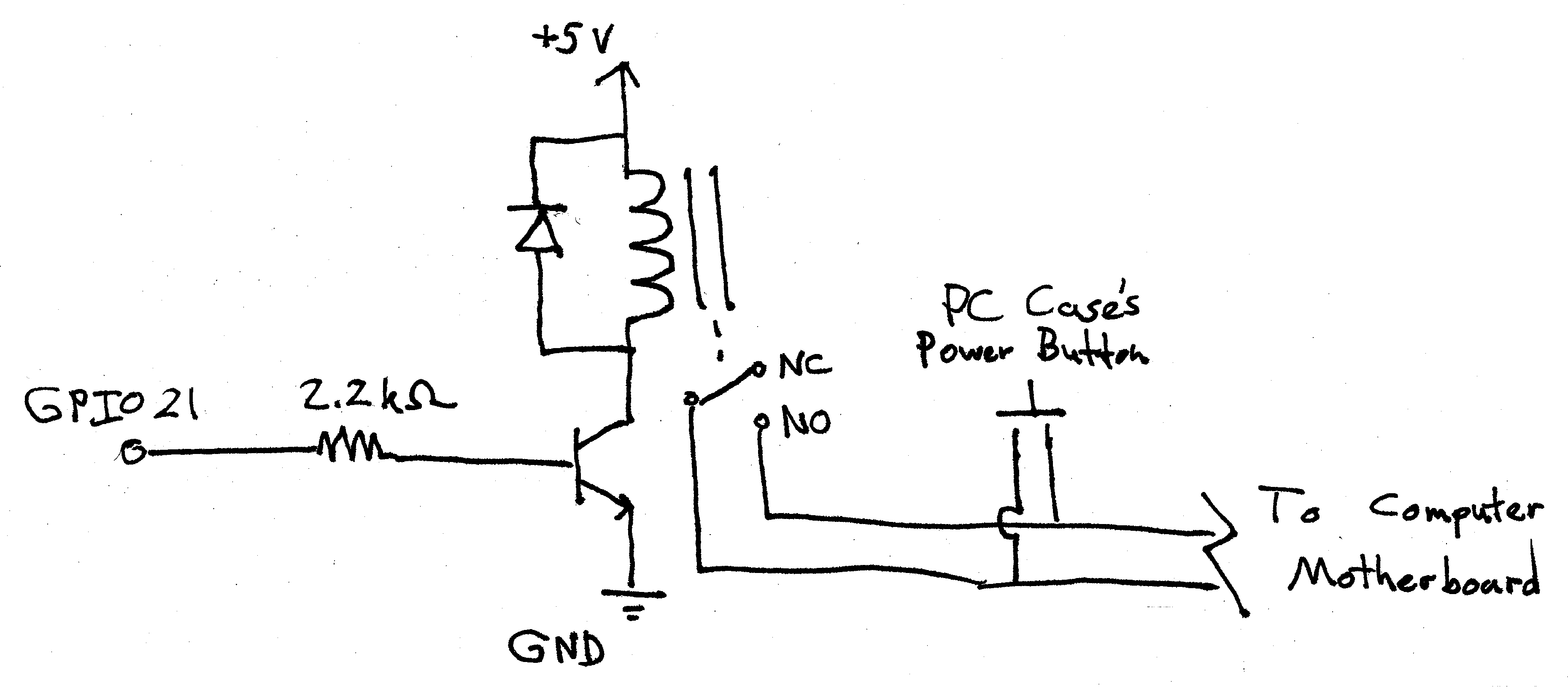
The heart of the project is a Raspberry PI 2 that I purchased some time back and never quite found a project for (better late than never). Tied to GPIO21 is a simple circuit consisting of a resistor, a transistor, a diode, and a relay, such that when the pin goes high, the relay closes. The relay is connected in parallel with the power button on my computer, so that either the relay or the button can be used to start it.

The Software
Running on the Raspberry Pi is a simple Python program based on a package called Flask-Ask, developed by a software engineer by the name of John Wheeler. This program, with the aid of a matching Alexa skill I named Management, evaluates the words the Alexa server sends its way and matches them to an action. Specifically, when it hears the words “computer” and “on,” it drives GPIO21 high for half a second and asks Alexa to respond to the voice command with “turning on computer.”

#management.py
from flask import Flask
from flask_ask import Ask, statement, convert_errors
import RPi.GPIO as GPIO
import logging
import time

GPIO.setmode(GPIO.BCM) #sets up script to address GPIO by GPIO pin names, not absolute position
GPIO.setup(21, GPIO.OUT) #sets pin 21 to an output; will be used to drive relay high to turn on computer

app = Flask(__name__)
ask = Ask(app, '/')

logging.getLogger("flask_ask").setLevel(logging.DEBUG)

@ask.intent('DeviceControlIntent', mapping={'status': 'status', 'device': 'device'})
def device_control(status, device):

if device in ['computer']: #user asks to control computer
if status in ['on', 'high']: #user asks to turn on computer
GPIO.output(21, GPIO.HIGH)
time.sleep(0.5)
GPIO.output(21, GPIO.LOW)
return statement('Turning on computer')
if status in ['off', 'low']: #user asks to turn off computer
return statement('Sorry. That function is unavailable')
else: #user asks to control a device not added to the if tree
return statement('Sorry. I cant seem to find that device')

if __name__ == '__main__':

port = 5000 #the custom port you want

app.run(host='0.0.0.0', port=port)

The First Run

Where To Go From Here
I’m not quite ready to button the Pi inside my computer permanently. I’d like to get my solderless breadboard back. More importantly, there are a couple more features I’d like to add before I call this one done.

1. Clean up the code. Turn instances of pin 21 in the code into a variable that’s set on start, etc, so that the code is easier to read, understand, and modify.
2. Tie one of the Pi’s pins to the 5V USB line of the computer, and add a check to the Management program. If the pin is high and the user asks to turn on the computer, Alexa responds with “the computer is already on” and the relay is not actuated.
3. Add a small microcontroller that can emulate a USB keyboard, and some more code so that the user can ask Alexa to lock the computer. The Pi can set a pin high, the microcontroller sees the pin go high, and Windows+L is typed by the microcontroller, locking the computer.
4. Use that same microcontroller to actuate a key macro that shuts down the computer when Alexa is asked to do so.

Beyond that, the Management program and Alexa skill will be the basis for a number of other automated devices and operations I have in mind. For instance, Management could be used to communicate with ethernet shield-equipped Arduinos in my apartment, reading off temperatures when asked, or actuating relays to turn on and off appliances (mostly lights). Hence why I decided to call it Management: in the future, it will manage my home.

The parts for the next phase of the project (some USB cables and an Adafruit Trinket) have already arrived. Stay tuned as Management gets smarter and more feature filled.

Categories: Projects
Dec
13

Emergency Nokia 2126 Phone Charger

Let me be the first to say that despite my love of all things high tech, I don’t really see the point in replacing a cell phone every year or so. I have been using a TracFone Nokia 2126 for the past 4 years. It used to belong to my father, which makes it about 8 to 10 years old. All I use it for is talking and the occasional text message. I have never spoken more than 60 minutes a month, and I have certainly never payed more than $200 a year for service. In fact, I use the thing so sparingly that I routinely let the battery go dead and forget to charge it for a day or two. However, it is only a matter of time before my phone sees more use. I will eventually have a full time job and when I do my employer and coworkers will probably be calling constantly. It would be nice to have a way to charge my phone on the go.

The above video has been making the rounds on tech and hacking blogs. In it, the uploader purchases a few parts from a Radio Shack and then uses the parts to build a battery-powered phone charger right on the store’s front counter. While it most certainly works, when I first saw the video the design kinda rubbed me the wrong way. Don’t get me wrong here, as it most certainly works, but I know that a much more versatile charger could be made by simply adding a voltage regulator. This way, a multitude of different batteries could be used to charge the phone.

This is a very simple project that you can easily do yourself. All the parts and tools can easily be had at a Radio Shack, assuming they have not eliminated their electronics components section. Also, with just a little tweaking, the charger could be made to work with numerous other phones.

Emergency Phone Charger

The Emergency Phone Charger in all its glory!

Parts List:
9V battery clip
Diode
0.1 μF capacitor
1 μF capacitor
LM317T adjustable voltage regulator
330 Ω resistor
1 kΩ resistor
150 Ω resistor
3.5 mm x 1.3 mm barrel plug (Radio Shack calls it a Size H plug)
Wire and breadboard

All we are doing is creating a voltage regulator circuit using the LM317T that outputs 5.7 volts, the voltage generated by the phone charger used to charge the Nokia 2126 and similar phones. The diode is used to keep the battery from being connected the wrong way and destroying the regulator. Remember that the tip of the barrel jack is center positive.

Phone Charger Schematic

Like I said: simple.

A switch, a case, and an LED to tell you that it is on and you are ready to talk for days: (sarcastic) woo! Better yet, you are prepared for any number of natural disasters that may knock out consumer power. Assuming the cell towers still have power (very likely as most telecommunication companies use back up generators of some type) you can keep in contact with family and emergency personell: (enthusiastic, Boy Scout “Be Prepared”) woo!

Categories: Projects
Nov
1

New Year’s Project List

1. Fix up the website. The colors look great on some computers and horrible on others. I may need some help in that regard.

2. Build a backup, solar-powered battery supply for my iPod Touch. I love my relatively new iPod. It replaces my too small iPod Nano and my Palm Tungsten T2, lets me check my email and favorite websites on the go, and I have just discovered the joy of watching “Top Gear” on it. Problem is, the battery lasts maybe a day or two before it needs to be recharged.

3. Send out resumes. It is time to be looking for a job.

4. Talk to someone who actually knows what it is like to be an engineer in the United States Air Force. I’m giving this particular career choice a serious amount of thought.

5. Finish the amplifier before the end of the school year. That includes revising the PCB, fabricating a cabinet, and figuring out why it keeps blowing fuses.

6. Do something neat with MATLab and an Arduino as part of an independent study.

7. Get rid of the leftover ArduinoBoy printed circuit boards.

8. With any luck, get myself published on the MAKE Magazine blog.

9. Get into a routine of posting at least once a month, or better yet twice a month.

10. Exercise more. Yes, a very common New Year’s resolution, but I could really use some exercise, especially if I go through with the Air Force job. Plus I wanted the list to be at least 10 items long.

Categories: Projects
Dec
27

What a Test!

It works. Wow does it work!

Went to the campus wood shop after class to cut the aluminum plates for the amplifier’s cabinet. It took several hours of cutting, filing, and drilling to create the three plates making up the bottom, the back, and the switch and fuse panel. However, it was worth it. With the plates fabricated, I had a basic chassis to attach the amplifier and its many support parts to.

I’ve been at it since marching band class ended 9:30 last night. Only finished it within the last hour. While the MAKE Magazine article suggested connecting a dummy load first and measuring the voltage across it, I could not get that to work. Instead, I jumped right into it and connected the amp to the speakers left over from my old boom box. I was greeted by a 440Hz sine wave coming out of Pure Data. I quickly moved on to a more “entertaining” test.

Amplifier Skeleton

Amplifier Skeleton

Wow. Just wow. Ross Hershberger wasn’t lying when he said this thing sounds like a million bucks. It’s just like listening to my dad’s 600W behemoth of a stereo back at home. If I closed my eyes, I could imagine myself front and center at an ELO concert, afros bobbing in time to “Latitude 88 North”. This amplifier is well worth the pain.

Unfortunately, my joy is tempered somewhat by two things. First off, I still don’t have a cabinet, and the amp takes up a fair bit of space on my work bench. Second, when there is no input signal, there is a bit of a low hum. It’s going to get old fast, and I don’t think I have the skills or know how to track down the source of the hum myself, but just having great sounding music in my dorm again more than makes up for it.

Have you built your own Bare Bones Amp? Maybe you have some insight into my noise problem. Feel free to post your comments and suggestions below.

EDIT: Just found one potential source of interference. I think the amplifiers may be creating a ground loop (a path in which two ends of a grounded node come back to each other). The mounting hardware I ordered to heat sink the ICs came with metal rather than nylon nuts and bolts. I figured it would be okay, however, because the kit also included a plastic washer that fits within the IC’s mounting holes, which I assumed was to keep the bolts from making contact with the IC chassis. Turns out the washer is doing bupkis. I’ll order some nylon hardware later this week and hope for the best. If you know any other reasons for the noise, however, by all means share. This may not be the only problem with my design.

Also, I found out why my initial tests failed: I had my voltohm meter set for amps instead of volts. Stupid.

Categories: Projects
Tags: ,
Nov
9

Getting the Board Together


I finally had some time this weekend to work on the amplifier board, and for your viewing pleasure, I recorded it with my iPod Touch.  It took a little less than 45 minutes to populate the board, but I sped up the video so you can see it completed in 4.  In building the circuit, however, I encountered a few errors that I will want to rectify in future versions of the board, should I decide to build another amplifier.  One or two of the components are a little too close for comfort.  At least two capacitors are in direct contact with each other, and two resistors have their solder pads close enough that an unskilled individual could easily bridge the gap.  Also, I haven’t been able to test the circuit just yet.  The idea of having a live 110V AC line exposed on my workbench makes me more than a little unsettled.  It appears I will not be able to test the circuit until I have a cabinet I can store it in.

Despite this, I’m quite proud of how the board came out.  I am one step closer to having a working stereo once again.

Categories: Projects
Tags: ,
Nov
1

Getting There


Board and Chips

Been a while since I updated the blog.  I’m going to have to try to get into a routine to try to post at least once a week.  In the meantime, the amplifier ICs arrived last week from Digi-Key and my custom board arrived this Monday.  I’ve also been sketching up different potential designs for the cabinet and made sure the campus wood shop has all the tools and supplies I need to make it.

Categories: Projects
Tags: ,
Oct
15

BBA Board Ready for Fabrication

Revised BBA Layout 9/20/10

Revised Bare Bones Amplifier

I had some free time this afternoon and was able to adjust my layout for the MAKE Bare Bones Amplifier.  The only real modifications I made was the removal of the ground plane in favor of a star ground connection and the re-maneuvering of a few parts to try to get the ground lines a little shorter.  Coincidentally, I will be sending out the fabrication files this evening to BatchPCB, a low-volume printed circuit board fabrication company.  With any luck, I should have the board in a week or two, ready to be populated.  If all goes well, I should have a working stereo again by the end of October.  As usual, stay tuned for future updates.

You can find a copy of the revised board and other BBA resources here.

In other news, you may have noticed that there is currently a single item for sale in the For Sale area of this site.  I finally finished up the last of the ArduinoBoys I had lying around on Friday and put them up for sale early Saturday morning.  Out of the initial 15 for sale, there is but one left.  This lone ArduinoBoy will be the last one I will be selling for some time, as I currently do not have the time in which to build anymore.  If you have been looking to buy an ArduinoBoy from me, this may be your last chance.

Categories: For Sale,Projects
Sep
20

MAKE Magazine Bare Bones Amplifier

MAKE Amplifier

Printed circuit board of the MAKE Issue 23 Amplifier Project.

Last winter, after returning to school from vacation, I turned on my computer and the boom box I had connected to it to watch some television with my computer’s TV tuner. Whilst in the middle of a particularly exciting episode of “Law & Order”, my stereo soon started to make some rather horrible noises. In a matter of moments, the RCA brand stereo that I had been using for almost 3 years to crank the tunes out of my iMac finally cut out completely, leaving me in a silent dorm room filling with the smell of burning electronics.

After taking apart the stereo, I quickly realized that I was in over my head. Like so many other things in this day and age, my stereo was not designed to be repaired, but rather to be thrown away and replaced. At the end of the semester, I put the stereo’s gutted carcass in the recycling bin on my dorm room floor, but hung onto the speakers, figuring I could buy a new amplifier instead. Unfortunately, according to my dad, a major audiophile himself, buying a new amplifier alone would set me back a pretty penny. The only other alternative would be to buy another boom box that would probably explode itself in another 3 years.

Fortunately, by a stroke of luck, this summer’s issue of MAKE Magazine (issue #23), contains a project called “Squelette, the Bare-Bones Amplifier”: a two-channel amplifier built from a pair of National Semiconductor LM1875 audio amplifier ICs and a number of discrete parts available from most RadioShacks with a well-stocked electronic parts aisle.  It was exactly what I was looking for.

Perhaps the only quibble I had with the BBA, however, was its use of perf board for a base.  Perf board is that printed circuit board material with all those grid holes in it and those solder pads that just don’t take solder all that well (at least for me they don’t).  Not only do I not like working with perf board, but I have become somewhat addicted to using EAGLE to make my own boards and have them fabricated by companies like BatchPCB or Gold Phoenix (an unfortunate side effect of my last project).

Today, I am pleased to present my schematic and board layout for my version of the MAKE Magazine Bare-Bones Amplifier, which I will soon be submitting to BatchPCB for fabrication.  You can find the files, along with a bill of materials and other important documents, here. Please note, however, that there are no instructions provided.  You can find instructions for building the amplifier in MAKE Magazine Issue #23.

My plan for my amplifier is to mount it inside a wooden box with a brass or aluminum bottom and back to help cool both the ICs and the transformer.  A light coat of stain and some varnish, perhaps a Plexiglas lid, and I will have a stereo again.  More importantly, I’ll have a stereo that I can fix myself and is supposed to sound exceptionally good.

EDIT: I decided to post my progress on the discussion board for the amplifier article.  The author of the article, Ross Hershberger, saw my board layout and had this to say:

Thanks for your interest in this article and for the work that you put into adapting it to your needs. I don’t have the reader to look at your PCB layouts. I want to warn about one thing. NatSemi is very specific about the handling of the grounds in the circuit. They specify star grounding to a central point for the power supply and audio circuit grounds. The input ground reference, power supply bypass caps, feedback, etc. should all have their currents carried to the 0V star ground on separate leads. The manufacturer warns that mixing currents could lead to noise, distortion and instability. Typical PCB ground plane practice allows currents to interact in unpredictable ways. The chip has an open loop gain of 90dbs and any spurious signals on the input or feedback circuits could be amplified.

Good thing I didn’t send the files off for fabrication yet.  I have to remove the ground plane and replace it with individual, dedicated lines between each grounded device and the two pins between the two 4700μF capacitors, or I’ll end up amplifying electrical noise as well.  This would be so much easier if they only taught printed circuit board design at Southern Illinois University at Carbondale.

Categories: Projects
Tags: ,
Aug
29